Mon Jan 15, 2024 Rounded Variants of Wagner VII
Updated on Thu Feb 29, 2024
Please excuse the delay in completing this blog post!
It’s still not quite finished
– but I wanted to publish at least part of it now.
Recently, I’ve added three projections to My Projection Collection. All of them were developed using Strebe’s transformation – called Substitute deprojection by its creator[1] – which is explained in a 2015[2] study as follows:
Strebe’s method consists of five steps:
(1) selecting and applying the projection to be modified (e.g., the Eckert IV);
(2) scaling the x and y coordinates by some factor chosen so that the range fits within the bounds of a second projection (e.g., the Mollweide);
(3) transform- ing the projected coordinates back on the sphere with the inverse of the second projection;
(4) transforming from the sphere to the new projected coordinate system with a third projection (e.g., the Hammer); and
(5) scaling the x and y coordinates by the reciprocal of the factor from step 2.
daan Strebe’s own 1995 projection was developed in this way utilizing the projections by Eckert, Mollweide and Hammer mentioned as examples in this explanation and applying the scaling factor s = 1.35.
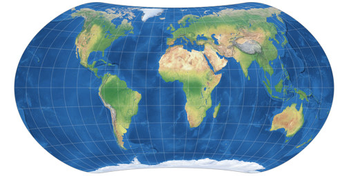
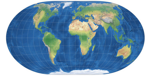
For use within the aforementioned study Bojan Šavrič and Bernhard Jenny created the Wagner VII with rounded corners to compare projections with edged pole line corners – e.g. the original Wagner VII – to projection which show curved corners. As far as I know, that was the new projections’ sole purpose, but it is a very fine piece of work and I would have added it earlier to my Projection Collection if I had had the means to create the needed images. But now, I have the means[3] – so here it is, the projection by Šavrič & Jenny! It uses Eckert IV both the first forward and the inverse, and Wagner VII for the second forward projection, with the scaling factor s = 1.15:
Shortly after I had found out how to render this projection, I talked to Peter Denner about it, and sent him a link to a demonstration of the Strebe transformation (taken from CanvasMap, a HTML framework to experiment with projection equations, programmed by Jenny, Šavrič, and El-Fouly), and after a few minutes of playing with that tool, Peter came up with a nice variant that we called Wagner VII, no corners, with point poles. Instead of Eckert IV as first forward and inverse, he used the Mollweide projection, and kept Wagner VII as second forward and s = 1.15:
And then I took Peter’s variant and set s to 1.03 which also leads to a point pole projections but one that looks very much as if it was a pole line projection. Then, I added another modification: Instead of using the famous Wagner VII version, I resorted to another variant that was also introduced in 1941 by Karlheinz Wagner[4] and that I have coined Wagner VII.b – so that’s the Wagner VII with rounded corners and point poles:
That’s the half-finished blog post.
Soon, I will explain how I arrived at precisely this
variant of the Wagner VII, no corners, with point poles.
References / Footnotes
-
↑
Strebe, Daniel (2018):
A bevy of area-preserving transforms for map projection designers.
available at researchgate.net -
↑
Šavrič, Bojan & Jenny, Bernhard & White, Denis & Strebe, Daniel. (2015):
User preferences for world map projections. Cartography and Geographic Information Science. 42. 398–409. 10.1080/15230406.2015.1014425. available at researchgate.net - ↑ To be honest, I had the means long ago: The Strebe transformation can be reproduced with a simple d3 script, and I had tried this a long time ago. But it just didn’t work. Then I left the script for a looong time, and when I went back to it, it took me about 10 seconds to figure out that it had been a simple typo. 😳
-
↑
Wagner Bros.
My introduction of Wagner’s own four variants of the Wagner VII.


 Except where otherwise noted, images on this site are licensed under
Comments
Be the first one to write a comment!